Overview
This was the final design project for MAE 162A (Introduction to Mechanisms & Mechanical Systems) at UCLA in Fall 2022. The brief: design a planar mechanism that carries a tabletop platform back and forth along a horizontal path, driven by a single rotating input link. The platform had to travel at least 850 mm, stay level, and barely move vertically while doing it.
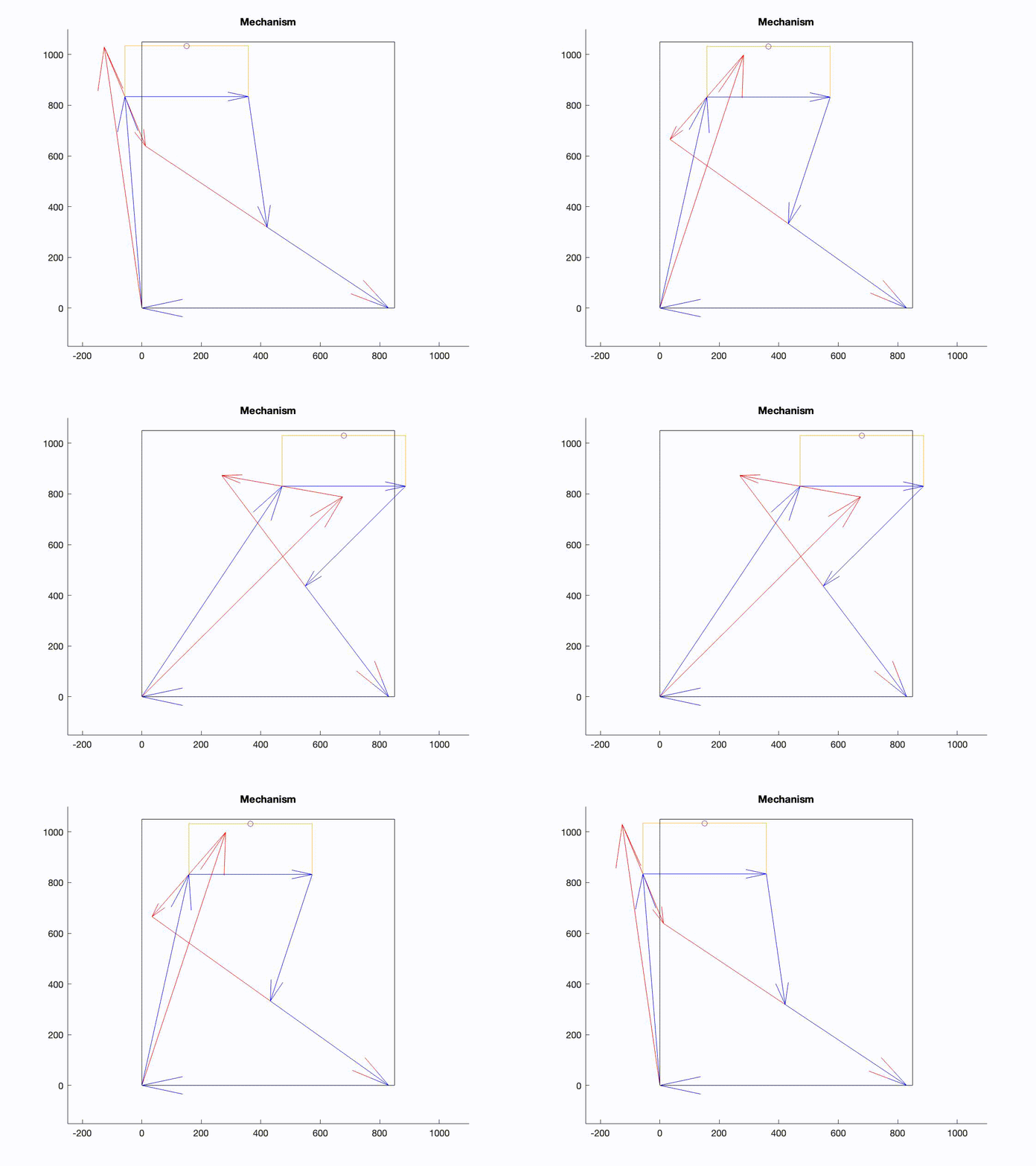
Our team of eleven built the design around a Chebyshev linkage, which turns rotation into nearly straight-line motion, and added a second kinematic loop to keep the platform parallel to the ground. I owned the MATLAB simulation and mechanism analysis: a small solver that takes the vector-loop equations, solves for every link angle at each input position, and animates the result. Those simulations set the link dimensions, which went into a SOLIDWORKS assembly.
The final design met every requirement: 850 mm of horizontal travel, less than 4 mm of vertical drift, and less than 0.001° of platform tilt, all inside an 850 mm × 1050 mm footprint.
Background
Turning rotation into straight-line motion sounds simple, but linkages that do it well only appeared during the Industrial Revolution. Watt's linkage (1784) traces an approximately straight line over part of its path. The Roberts and Chebyshev linkages followed with better straight sections, and true straight-line linkages like the Peaucellier–Lipkin (1864) came later.
A Chebyshev linkage is a four-bar mechanism: two equal-length rockers joined by a shorter coupler link. With the coupler, ground, and rockers in a 2 : 4 : 5 ratio, the midpoint of the coupler traces a path that is almost perfectly straight over a limited range of input angles. The deviation is never exactly zero, but it can be made small enough to be useful. That's why it suited this project: no sliders, no cams, just pin joints.
Design
The design specs for the platform (link 6), over the working range of the input angle θ₂:
- At least 850 mm of horizontal travel
- Less than 4 mm of vertical motion at the platform's center of mass
- Less than 1° of tilt from horizontal
- The whole mechanism must fit inside an 850 mm × 1050 mm box in at least one position
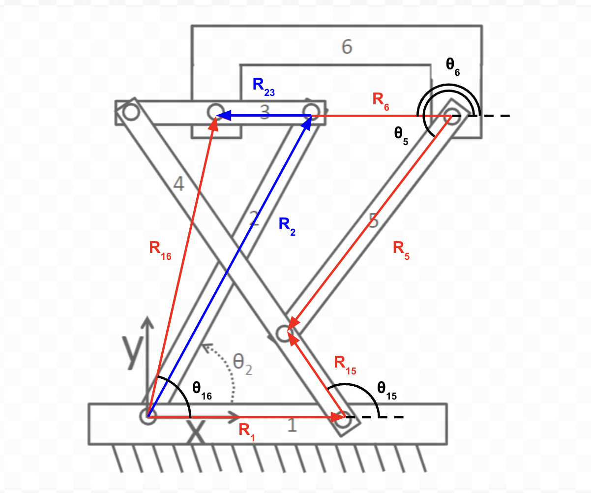
Links 1 through 4 form the Chebyshev four-bar in the standard proportions. Link 5 is half the length of link 2 and pins to its midpoint, so its free end stays level with the midpoint of the coupler. Together those two points form a vertical base that holds the tabletop level. The tabletop is as wide as the coupler and half as tall, which keeps the assembly inside the footprint. Setting the ground link to 800 mm scaled everything else:
- Link 1 (ground): 800 mm
- Link 2 (input rocker): 1000 mm
- Link 3 (coupler): 400 mm
- Link 4 (rocker): 1000 mm
- Link 5: 500 mm
- Link 6 (platform): 400 mm × 200 mm
After the simulation confirmed these dimensions, the links were modeled and assembled in SOLIDWORKS.
Analysis
The mechanism is described by two vector loops. The first is the four-bar itself:
R₂ + R₃ − R₄ − R₁ = 0
The second runs through link 5 to the platform, pinned at the midpoint of link 2, passing through the midpoint of link 3, and constrained so one of its vectors stays parallel to link 4 (θ₁₅ = θ₄). Splitting each loop into x and y components gives four nonlinear equations in the unknown angles for any given input θ₂.
I wrote a MATLAB class, MAE162A, that builds these loops symbolically, solves them at each input angle, and plays back the result as an animation. The core is a Newton–Raphson iteration on the loop equations using their symbolic Jacobian:
function sol = NRsolve(f1, f2, angles, guess, depth)
  J = jacobian([f1 f2], sym(angles));
  F = -inv(J)*[f1; f2];

  for i = 1:depth
      guess = (F(guess(1), guess(2)) + guess);
  end
  sol.(angles(1)) = mod(guess(1), 2*pi);
  sol.(angles(2)) = mod(guess(2), 2*pi);
end
The same class finds velocities from the loop's kinematic coefficients, traces the position and orientation of the platform, and records animations of both loops, so we could see link collisions or wrong solution branches immediately instead of finding them later in CAD. The repo also includes a Julia version of the solver, Mechanism.jl.
Results
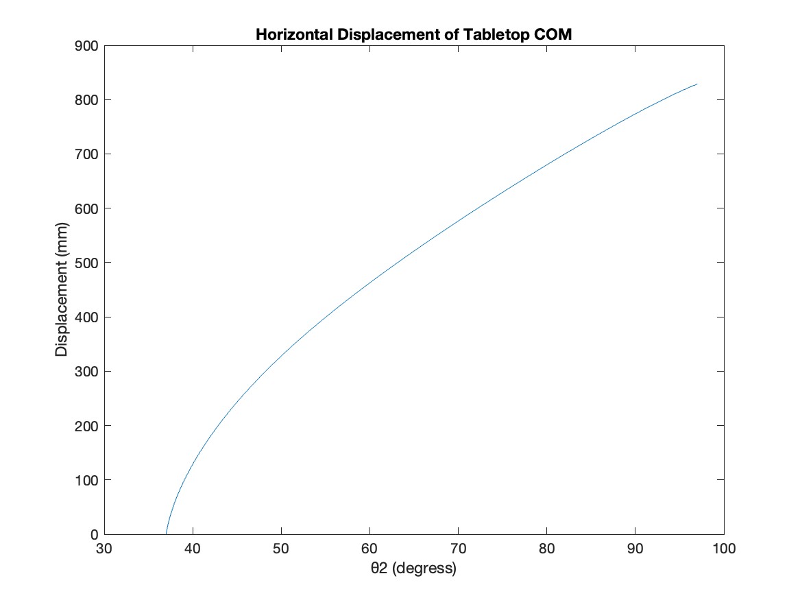
The platform reaches its far-right position at θ₂ = 37° and its far-left position at θ₂ = 97°. Over that 60° sweep its center of mass travels the full 850 mm. Displacement rises quickly between 37° and 45°, then is close to linear for the rest of the range.
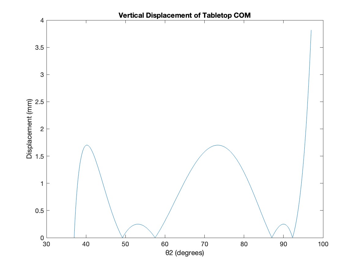
Vertical drift follows a roughly sinusoidal pattern, with peaks around 1.75 mm and 0.25 mm in the middle of the stroke and a rise to the 4 mm limit only at the very end of travel.
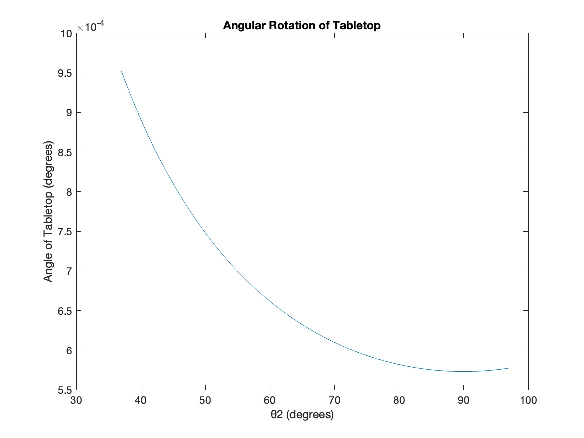
The platform's tilt was tiny: its worst cases are at the two ends of travel and are on the order of 10⁻⁴ degrees, far below the 1° limit.
Finally, we calculated the input torque needed to drive the mechanism through three full cycles. Because link 2 swings back and forth instead of rotating fully, the motor has to drive in both directions. Peak torque was about 0.029 N·m one way and 0.01 N·m the other. The mechanism needs less torque in the counterclockwise direction, probably because its center of mass already tends to fall that way.
Conclusion
The hardest part wasn't writing the vector loops. It was getting the platform across the full distance without letting it rotate, and making sure the coupler never swung up through the tabletop. Once we used the Chebyshev ratios, getting straight-line motion was easy. The real work was coordinating the two loops so that both stayed valid over the whole stroke.
On my side, the biggest lesson was how much a fast simulation loop speeds up mechanical design. Being able to change a ratio and see the full animation within seconds meant we settled on dimensions before anyone opened SOLIDWORKS. With more time, I'd add the solver's dimension search as an optimization step, aiming for a design that meets the specs with a larger margin, especially at the end of travel where vertical drift reaches the limit.